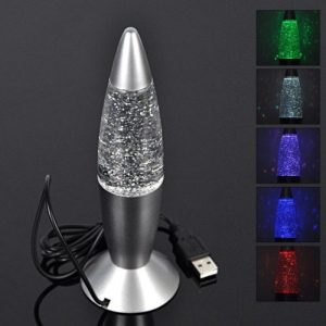

I found the lava lamp shown to the right, which is equipped with a color-changing LED and is powered from USB. I bought one and intended to modify the controlling electronics to my purposes.


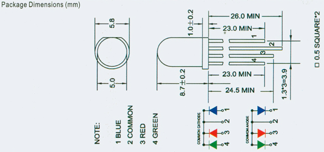
What I needed now is some control electronics, that can interface to USB, can be programmed from the computer, and control the color of a colored LED. A friend of mine told me about the Picaxe microcontroller as an easy way to receive serial signals and which also has digital or analog outputs to control an LED. Therefore, this is what I came up with:
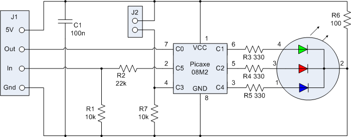

- VDD, 5V
- Serial out
- Serial in
- VSS, or Ground, or 0V
J2 corresponds to SW1 and it can be used for doing whatever the Picaxe can be programmed to do with it. Maybe it can start a fixed color-changing program, or it can turn the LED on or off.
R6 is a power resistor supposed to warm the lava lamp water a little, so that the glitter in the water gets moving.
Now I need a USB-to-serial adapter. I bought this one, whose fat plug I removed and soldered the 
With this construction, I end up with a USB device that announces itself to the computer as a serial COM port, which is attached to the Picaxe microcontroller. The Picaxe can be programmed with the help of the normal “Picaxe Editor 6″ IDE. I will talk about the necessary firmware programming in another article.
As a conclusion, one can say that my project idea requires mastery of the following three challenges:
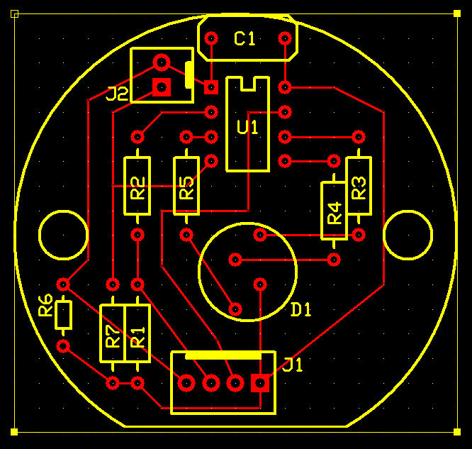
- The Hardware must be built. I described this process here roughly.
- The Firmware for the Picaxe must be written. This is a piece of software, that reads the desired color combinations from the USB port and lights up the three colors of the LED accordingly. I wrote this firmware already.
- The Software, that sends the necessary color codes to the USB port as a result of more or less complex events in the computer has only just begun its development phase. I am afraid that this part has the greatest complexity. In other words, it is possible to invest a huge amount of effort in order to create a more or less luxurious thing. This part may never really be finished. 🙂